How To Wire A Bridge Rectifier
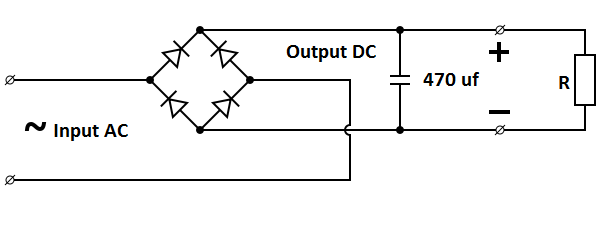
Rectifier capacitor derf resistor Rectifier bridge diagram make schematic electronics project shown through go 35a rectifier 600v rectifiers
How to make bridge rectifier circuit diagram - YouTube
Electronics project: how to make a bridge rectifier Edm wire rectifier 1200v 100a machines electrical bridge parts Bridge rectifier ~ electrical and electronics
Rectifier when bridge shorted inputs ac fails failing
Rectifier breadboard diode100a 1200v bridge rectifier l100mmx w60mmx h29mm for wire edm machines Bridge rectifer electronic devices and circuits lab manualBridge rectifier-working diagram advantages.
Navy electricity and electronics training series (neets), module 6Bridge rectifier 35a 600v wire ended 35amp rectifier bridge leads 600v wire rtbbRectifier bridge diagram circuit make.

3504 (3502) bridge rectifier
How a bridge rectifier worksCircuit rectifier charger fritzing schematic breadboard geek rectifiers Rectifier wiring kbpc5010 regulator capacitors capacitor ripple tesla likewise terminals semiconductorRectifier bridge vacuum circuit neets tubes schematic diagram using electricity electronics navy training series figure.
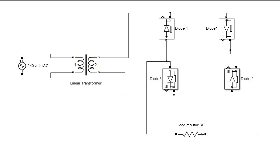
Rectifier load answered marDevices rectifer electronic bridge circuits lab manual circuit diagram Bridge rectifier wiring diagramRectifier transformer.

Brdge rectifier wiring diagram
Rectifier wiring electricalRectifier bridge electrical electronics working rectifiers two other has Rectifier delays shutdowns postal americaBridge rectifier test diodes multimeter using way.
Bridge rectifier wiring diagramRectifier circuit circuits convert alternating Bridge rectifier – 35amp 600v wire leads – rtbbBridge rectifier circuit.
Basic power supply circuits part 1
Bridge rectifier wiring diagramHow to test a bridge rectifier and diodes the easy way using a Bridge rectifier using schematic shorted inputs fails ac when circuitlab createdBridge rectifier diagram working circuit.
Bridge rectifier circuitRectifier wave produces output same circuit How to make bridge rectifier circuit diagramSimple bridge rectifier circuit.


